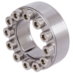
Material: Stainless steel 1.4401 (AISI 316).
Clamping bush for lower torques; not self-centering.
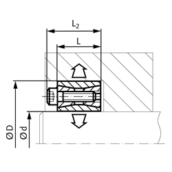
Fit: Shaft h8, Hub H8. Surface roughness Rz max. 16 µm.
Mounting: Slightly oil the clamping set before mounting, do not use molibdenum disulphide or grease. Tighten the screws evenly and crosswise in several steps. Demounting: Due to the cone angle, the clamping set is usually released once all screws have been fully unfastened. There a three large threads cut into the front ring, which serve to remove this ring.
Ts - Fastening Torque
T - Transmittable Torque
F - Transmittable Axial Force
P - Surface Pressure onto Hub
services: online CAD catalog
The supplied 3D models, pictures and technical drawings are made with reasonable care. Nevertheless liability is excluded for the accuracy and correctness of this data.
| part number | d [mm] |
D [mm] |
L [mm] |
L2 [mm] |
Übertragbares Drehmoment T [Nm] |
Axial Force Fax [kN] |
Surface Pressure Shaft PW [N/mm²] |
Surface Pressure Hub PN [N/mm²] |
Clamping Bolts DIN 912 [N. x Typ] |
Torque Ms [Nm] |
Gewicht [kg] |
|
|---|---|---|---|---|---|---|---|---|---|---|---|---|
| 61599514 | CAD | 14 | 42 | 20 | 26 | 95 | 14 | 154 | 51 | 8 x M6 | 8 | 0,18 |
| 61599515 | CAD | 15 | 42 | 20 | 26 | 95 | 14 | 148 | 53 | 8 x M6 | 8 | 0,18 |
| 61599516 | CAD | 16 | 44 | 20 | 26 | 100 | 14 | 135 | 53 | 8 x M6 | 8 | 0,18 |
| 61599517 | CAD | 17 | 44 | 20 | 26 | 105 | 14 | 125 | 49 | 8 x M6 | 8 | 0,18 |
| 61599518 | CAD | 18 | 47 | 20 | 26 | 110 | 13 | 102 | 43 | 8 x M6 | 8 | 0,18 |
| 61599519 | CAD | 19 | 47 | 20 | 26 | 130 | 15 | 119 | 50 | 8 x M6 | 8 | 0,18 |
| 61599520 | CAD | 20 | 47 | 20 | 26 | 160 | 16 | 124 | 52 | 8 x M6 | 8 | 0,21 |
| 61599522 | CAD | 22 | 47 | 20 | 26 | 180 | 16 | 107 | 48 | 8 x M6 | 8 | 0,2 |
| 61599524 | CAD | 24 | 50 | 20 | 26 | 215 | 17 | 114 | 54 | 8 x M6 | 8 | 0,22 |
| 61599525 | CAD | 25 | 50 | 20 | 26 | 230 | 17 | 108 | 54 | 8 x M6 | 8 | 0,22 |
| 61599528 | CAD | 28 | 55 | 20 | 26 | 300 | 19 | 110 | 55 | 10 x M6 | 8 | 0,27 |
| 61599530 | CAD | 30 | 55 | 20 | 26 | 330 | 19 | 97 | 52 | 10 x M6 | 8 | 0,25 |
| 61599532 | CAD | 32 | 60 | 20 | 26 | 420 | 23 | 112 | 60 | 12 x M6 | 8 | 0,3 |
| 61599535 | CAD | 35 | 60 | 20 | 26 | 520 | 23 | 104 | 60 | 12 x M6 | 8 | 0,29 |
| 61599538 | CAD | 38 | 65 | 20 | 26 | 650 | 26 | 107 | 62 | 14 x M6 | 8 | 0,33 |
| 61599540 | CAD | 40 | 65 | 20 | 26 | 700 | 26 | 101 | 61 | 14 x M6 | 8 | 0,32 |
| 61599545 | CAD | 45 | 75 | 24 | 32 | 750 | 37 | 105 | 62 | 12 x M8 | 18 | 0,53 |
| 61599550 | CAD | 50 | 80 | 24 | 32 | 1000 | 36 | 95 | 57 | 12 x M8 | 18 | 0,56 |
| 61599555 | CAD | 55 | 85 | 24 | 32 | 1400 | 43 | 106 | 68 | 14 x M8 | 18 | 0,65 |
| 61599560 | CAD | 60 | 90 | 24 | 32 | 1500 | 45 | 93 | 61 | 14 x M8 | 18 | 0,66 |
| 61599565 | CAD | 65 | 95 | 24 | 32 | 1800 | 48 | 98 | 66 | 16 x M8 | 18 | 0,72 |
| 61599570 | CAD | 70 | 110 | 28 | 38 | 2200 | 62 | 109 | 68 | 14 x M10 | 35 | 1,27 |
| 61599575 | CAD | 75 | 115 | 28 | 38 | 2400 | 68 | 93 | 60 | 14 x M10 | 35 | 1,33 |
| 61599580 | CAD | 80 | 120 | 28 | 38 | 2600 | 68 | 93 | 62 | 14 x M10 | 35 | 1,35 |